Data Link Layer
access to the physical layer.
- identify devices - addressing
- structure and frame the raw bitstream
- Detect and correct bit errors
- Control access to the channel
Interface with Layer 1(Physical Layer)
- raw bitstream
Interface with Layer 3(Network Layer)
- structured communication (addressing, packets)
Basic Services
Addressing
- Physical links can be:
- multi-access can be Wireless links, but several hosts can also be connected to a single cable to form multi-access wired link. Also, require host addresses, to identify senders and receivers.
- point-to-point links connect individual pairs of machines.
- hosts addresses may be:
- local-link - sufficient to be unique only amongst devices connected to a link, but needs coordination between devices to assign addresses
- global Scope - Simpler to implement if devices can move, since don’t need to change address when connected to a different link – privacy concerns
Framing
- physical layer provides unreliable raw bit stream as:
- bits might be corrupted
- timing can be disrupted
- Data link layer must correct these errors by:
- Break the raw bit stream into frames
- Transmit and repair frames
- limit scope of any transmission errors an example can be Ethernet
Synchronisation
Detecting the start of a message methods include:
- Gap based detection
- Method: leaving gaps between frames to indicate the start of a new message
- Problem: the physical layer doesn’t always guarantee perfect timing
- Length Field Precedence
- Method: precede each frame with a length field to indicate the size of the frame
- Problem:if the length field is corrupted, it becomes difficult to locate the next frame
- Start Code Insertion
- Method:add a special start code (a unique bit pattern) at the beginning of each frame
- Problem:this unique pattern only occurs at the start of frames, allowing the receiver to synchronise after an error. The receiver waits for the next start code and begins reading frame headers. What if the start code appears within the data?
Bit stuffing
The sender inserts a ‘0’ bit after sending any sequence of five consecutive ‘1’ bits, unless it sending the start code
- Receivers action:
- If the receiver sees five consecutive ‘1’ bits, it checks the sixth bit:
- If the sixth bit is ‘0’, it has been stuffed, so the receiver removes it
- If the sixth bit is ‘1’, the receiver checks the seventh bit:
- If the seventh bit is ‘0’, it identifies the start code
- If the seventh bit is ‘1’, the frame is considered corrupted
- If the receiver sees five consecutive ‘1’ bits, it checks the sixth bit:
this method acts as a binary-level escape code, ensuring that the start code remains unique and correctly identified
Error Detection and Correction
Noise and interference at physical layer can cause bit errors
- Rare in wired links, common in wireless systems.
- add error detecting code to each packet an Examples
Error detection codes include:
- parity code
- The Internet checksum
- CRC^[CRC (Cyclic Redundancy Code) ▪ Error detecting code used to identify data corruption ▪ Generates a short binary sequence (the CRC value) from data using polynomial division and appends it to the data ▪ The receiver checks for errors by recalculating and comparing the CRC value]
error detection and error correction are the main ways to validate data.
Media Access Control
the protocols that determine how data is transmitted between devices and regulate the access over a shared communication medium, ensuring that data packets are transmitted efficiently and without collision.
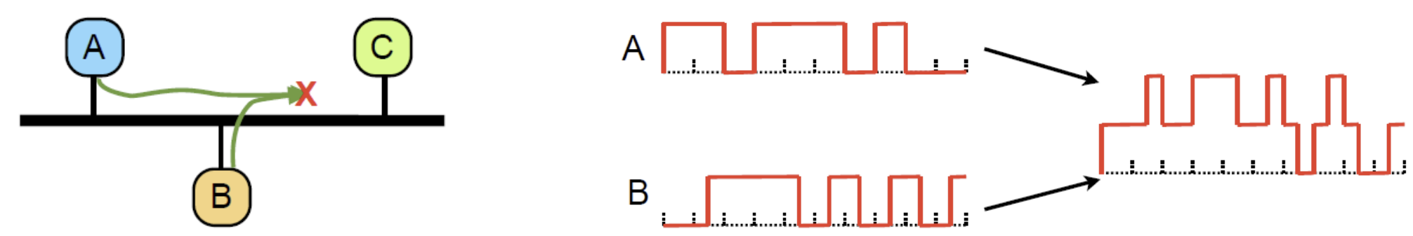
Link contention
when Two hosts transmit simultaneously → Collision
- the Signals overlap: only garbage received
Contention Based MAC
Multiple hosts share channel in a way that can lead to collisions: system is contention-based In contention-based MAC, multiple devices “contend” for the opportunity to transmit data. Here are the key characteristics and examples of contention-based MAC:
-
No Centralized Control: There is no central authority to manage access to the medium. Each device independently decides when to attempt transmission.
-
Collision Handling: Since multiple devices may attempt to transmit simultaneously, collisions can occur. Contention-based MAC protocols include mechanisms to detect and handle these collisions.
Examples include:
- CSMA/CD (Carrier Sense Multiple Access with Collision Detection): Used in Ethernet networks. Devices listen to the medium before transmitting (carrier sense) and detect collisions. If a collision is detected, devices stop transmitting and wait for a random backoff^[Backoff time is a mechanism used in networking to manage data transmission attempts after a collision occurs on a shared communication medium] time before trying again.
- CSMA/CA (Carrier Sense Multiple Access with Collision Avoidance): Used in wireless networks like Wi-Fi. Devices attempt to avoid collisions by using techniques such as waiting for a random backoff time before transmitting and using acknowledgments to confirm successful transmissions.
Terminology
ARP^[ARP (Address Resolution Protocol) ▪ Used to map an IP address to a MAC address on a local network, enabling proper packet routing ▪ When a device needs to send data to another device on the same network, but only knows its IP address, ARP helps determine the corresponding MAC address ▪ The device sends out an ARP request packet, which is broadcasted to all devices on the local network, essentially asking: “who has this IP address?” ▪ The device with the matching IP address responds with an ARP reply, providing its MAC address, allowing the sender to address packets correctly at the data link layer]